Raspberry Pi and KY040 Rotary Encoder
For a Raspberry Pi powered vintage radio build I’m doing I wanted to replace the original tuning dial with a turning switch which I could use to skip tracks backwards and forwards.
Being notoriously tight I opted for the VERY cheap KY040 (Amazon UK, US) rotary encoder module (less than £1 from the right stores). What a didn’t realise when I brought it was that it doesn’t use the typical ‘gray code’ for its encoding - this led to more than a few hours of frustration, so here is some setup and code to save you from the same!
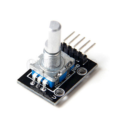
Stock picture not released under creative commons.
The KY040 has 5 pins:
- GND - ground
-
-
- 3.3v
-
- SW - switch
- DT - data
- CLK - clock
The SW pin is the switch pin and goes high when the rotary encoder is pushed.
The CLK (clock) and DT (data) pins are how you read the direction the encoder has been turned. The CLK pin goes low when the encoder has been turned and the DT pin shows which was it has been turned, low for clockwise, high for anti clockwise.
The SW, CLK and DT pins should be connected to GPIO pins on the and Pi, the + and GND are pretty self explanatory and should be connected to a 3.3v and ground pin.
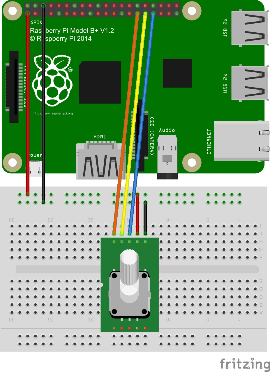
I connected CLK to GPIO 5, DT to GPIO 6 and SW to GPIO 13.
The code uses RPi.GPIO’s edge detection functions to trigger a callback when the CLK pin goes low and then reads the value from the data pin to work out if it was turned clockwise or anti-clockwise.
The code repository is on github https://github.com/martinohanlon/KY040.
There is a class, KY040, which expects the GPIO pins to be passed and 2 callback functions which are called when the dial is turned or the switch is pressed.
#KY040 Python Class
#Martin O'Hanlon
#stuffaboutcode.com

import RPi.GPIO as GPIO
from time import sleep

class KY040:

    CLOCKWISE = 0
    ANTICLOCKWISE = 1

    def __init__(self, clockPin, dataPin, switchPin,
                 rotaryCallback, switchCallback):
        #persist values
        self.clockPin = clockPin
        self.dataPin = dataPin
        self.switchPin = switchPin
        self.rotaryCallback = rotaryCallback
        self.switchCallback = switchCallback

        #setup pins
        GPIO.setup(clockPin, GPIO.IN)
        GPIO.setup(dataPin, GPIO.IN)
        GPIO.setup(switchPin, GPIO.IN, pull_up_down=GPIO.PUD_UP)

    def start(self):
        GPIO.add_event_detect(self.clockPin,
                              GPIO.FALLING,
                              callback=self._clockCallback,
                              bouncetime=250)
        GPIO.add_event_detect(self.switchPin,
                              GPIO.FALLING,
                              callback=self._switchCallback,
                              bouncetime=300)

    def stop(self):
        GPIO.remove_event_detect(self.clockPin)
        GPIO.remove_event_detect(self.switchPin)

    def _clockCallback(self, pin):
        if GPIO.input(self.clockPin) == 0:
            data = GPIO.input(self.dataPin)
            if data == 1:
                self.rotaryCallback(self.ANTICLOCKWISE)
            else:
                self.rotaryCallback(self.CLOCKWISE)

    def _switchCallback(self, pin):
        if GPIO.input(self.switchPin) == 0:
            self.switchCallback()

#test
if __name__ == "__main__":

    CLOCKPIN = 5
    DATAPIN = 6
    SWITCHPIN = 13

    def rotaryChange(direction):
        print "turned - " + str(direction)
    def switchPressed():
        print "button pressed"

    GPIO.setmode(GPIO.BCM)

    ky040 = KY040(CLOCKPIN, DATAPIN, SWITCHPIN,
                  rotaryChange, switchPressed)

    ky040.start()

    try:
        while True:
            sleep(0.1)
    finally:
        ky040.stop()
        GPIO.cleanup()
You can buy the same rotary encoder without the module but you will have to add pull ups to the CLK and DT pins.